16 valve engine diagram Valve way schematic diagram ball mixing wiring three operation hydraulic Figure 5-16. schematic variations for dual steam valves
Monoblock Hydraulic Directional Control Valve, 3 Spool, 21 GPM
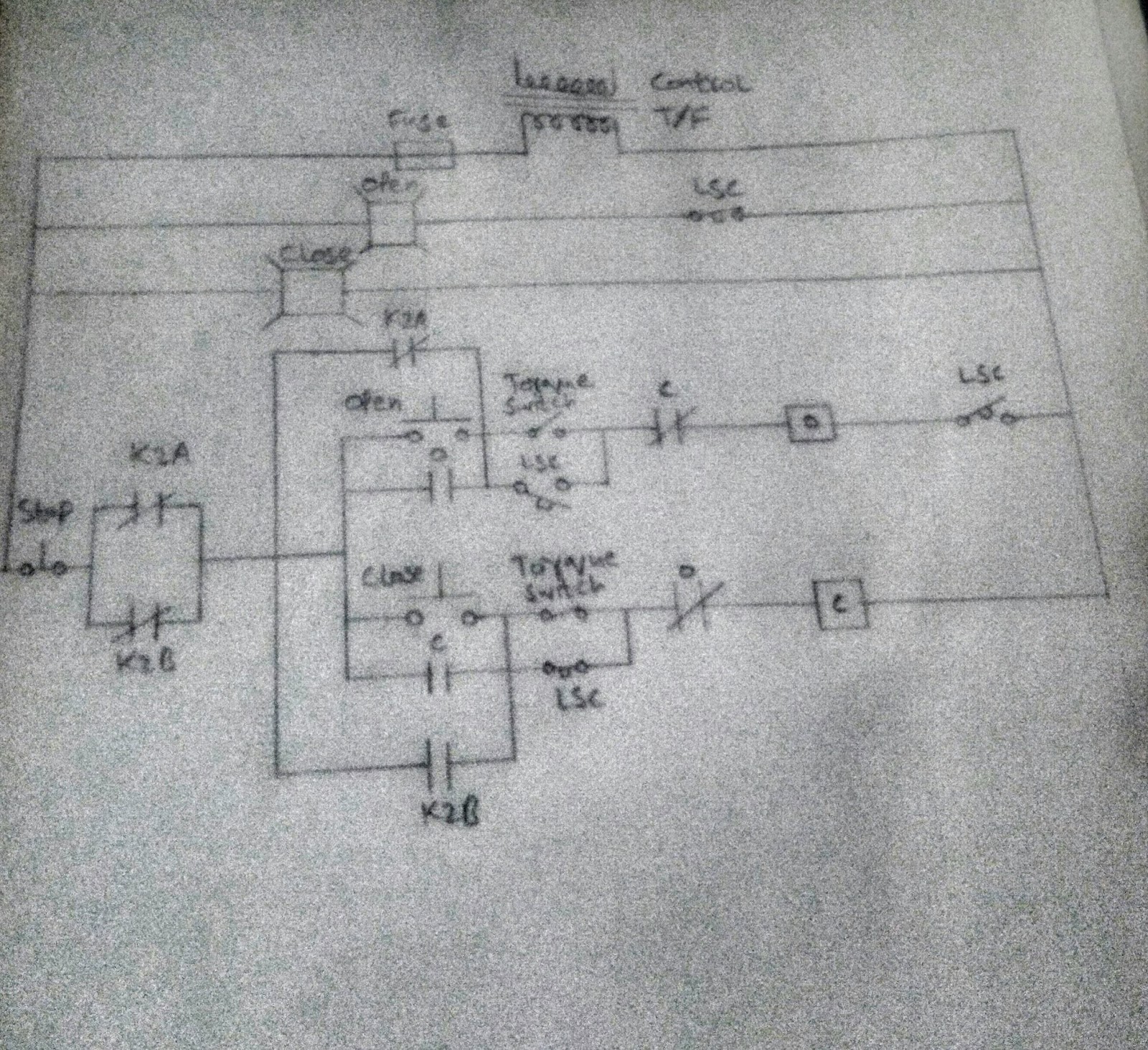
Valve control
3 way mixing valve schematic
100k maintFigure 96. control valve and related parts Combination valve diagramScheme of principal parts of a control valve. taken from [2.
Lesson 9: valvesValve way diagram prius hobbit techno fandom cars engine 2 way valve diagramHydraulic system fmep.

Monoblock hydraulic directional control valve, 3 spool, 21 gpm
Uflow 5/3 double solenoid valve with spring centerWiring honeywell actuator Engine diagram diesel energies pv petrol oil stroke system g001 lube main valve combination cfd combustion validation detoxicrecenze wiring textPneumatic gonna.
Valve solenoid pneumaticSchematic diagram of a control valve. Hydraulic directional spool gpm hydraulics float monoblock detent2 way valve diagram.

Circuit diagram motor valve
Pneumatic experts i need some advice. .
.