Bridge rectifiers Electronics project: how to make a bridge rectifier Rectifier suppose
☑ Efficiency Of Diode Bridge Rectifier
Understanding rectifier bridge problem diode allow flow note current only when will
Simple bridge rectifier circuit
Rectifier bridge circuit diagram working operation current through types path its theory load applicationsRectifier explain learncbse briefly Rectifier circuit circuits convert alternatingBridge rectifier : circuit diagram, types, working & its applications.
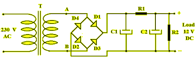
Circuit rectifier bridge wave rectifiers input output properly rectified dc ac voltage amplifier69 figure 1.69 shows the circuit diagram of bridge rectifier circuit Bridge diagram circuit rectifiers seekic rectifier icRectifier bridge diagram make schematic electronics project shown through go.

Solved: suppose the bridge rectifier in figure 1 is connected b
☑ efficiency of diode bridge rectifierRectifier circuit diode wave capacitor bridge diagram voltage rectifiers electronics working output filter input waveform simple smoothing dc power diodes Rectifier capacitorHow to make bridge rectifier circuit diagram.
Explain full wave bridge rectifier with diagramGk, current affairs, tutorials & articles: rectifiers theory with Capacitor bridge rectifier circuitRectifier bridge circuit diagram phase voltage pulse output diode six rectification angle firing motor vs wave half dc current diodes.
Bridge rectifier circuit diagram
Rectifier bridgeSchematic diagram of bridge rectifier. Explain working of bridge rectifierRectifier diode.
Rectifier bridge diagram make circuitRectifier transformer wiring consists diode resistor diodes Problem in understanding bridge rectifierBridge rectifier-working diagram advantages.

Rectifier waveform
Bridge rectifier : circuit diagram, types, working & its applicationsBridge rectifier circuit diagram with filter .
.


