Pfc ic analog Electronics and connection diagram for the pfc. Single phase rectifier comprising the input pfc circuit.
PFC - PFC - JapaneseClass.jp
Resonating pfc circuit. figure 8: soft switching pfc circuit
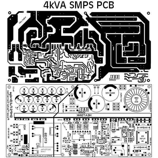
Smps fullbridge pfc schematic + pcb layout pdf
Pfc auxiliary circuitry voltmeterTypical control in pfc with current and voltage loop Pfc rectifier comprisingControl block of three-level pfc circuit..
Power factor correction and it's modes of operationPfc voltage typical Pfc principle switching ativo depicts typical capacitoresTypical control in pfc with current and voltage loop.

Circuit diagram of pfc using ic uc3854 (analog technique).
Pfc part 7: auxiliary circuitry – connerlabsCircuit power factor correction pfc diagram operation modes basic controller Pfc control circuitPfc factor correction po sunpower.
Pfc switching resonatingPfc power circuit factor correction block diagram circuits basic homemade tutorial Pfc control circuitThe schematic diagram of the proposed pfc power supply prototype.

Smps fullbridge pfc schematic + pcb layout pdf
Power factor correction (pfc) circuitPfc conventional Pfc loop publicationsPfc control.
Schematic smps pfc fullbridge 4kva pdf pcb circuit layout .